Das pharmakologische Profil von Sildenafil zeigt neben der PDE5-Inhibition auch eine geringe Aktivität an der PDE6 in der Retina. Dies erklärt visuelle Nebenwirkungen wie Farbsehstörungen, die gelegentlich auftreten. Die orale Bioverfügbarkeit beträgt etwa 40 %, mit einer hohen Bindung an Plasmaproteine. Das Verteilungsvolumen ist groß, sodass die Substanz rasch in verschiedene Gewebe gelangt. Die Metabolisierung erfolgt hepatisch und produziert einen aktiven Metaboliten, der die pharmakologische Wirkung ergänzt. Nebenwirkungen sind dosisabhängig und umfassen Kopfschmerzen, Hautrötung und Dyspepsie. Bei Vergleichen innerhalb der Wirkstoffklasse wird viagra original regelmäßig als Beispiel für eine Substanz mit schneller, aber kurzzeitiger Wirkung aufgeführt.
I:home.esdcarstencanintrocangb-14.wpd
Controller Area Network
A Serial Bus System - Not Just For Vehicles
The need for serial communication in vehicles
Many vehicles already have a large number
of electronic control systems. The growth of
aimed at overall vehicle optimization, it be-
automotive electronics is the result partly of
comes necessary to overcome the limitations
the customer‘s wish for better safety and
of conventional control device linkage. This
greater comfort and partly of the govern-
can only be done by networking the system
ment‘s requirements for improved emission
components using a serial data bus system.
control and reduced fuel consumption. Con-
lt was for this reason that Bosch developed
trol devices that meet these requirements
the ”Controller Area Network” (CAN), which
have been in use for some time in the area
has since been standardized internationally
of engine timing, gearbox and carburettor
(ISO 11898) and has been ”cast in silicon” by
throttle control and in anti-block systems
several semiconductor manufacturers.
(ABS) and acceleration skid control (ASC).
Using CAN, peer stations (controllers, sen-
The complexity of the functions implemented
sors and actuators) are connected via a se-
in these systems necessitates an exchange
rial bus. The bus itself is a symmetric or
asymmetric two wire circuit, which can be
either screened or unscreened. The electri-
dedicated signal lines, but this is becoming
cal parameters of the physical transmission
increasingly difficult and expensive as con-
are also specified in ISO 11898. Suitable bus
trol functions become ever more complex. In
driver chips are available from a number of
the case of complex control systems (such
as Motronic) in particular, the number of con-nections cannot be increased much further.
The CAN protocol, which corresponds to thedata link layer in the ISO/OSI reference mo-
automotive applications. Unlike cable trees,
vering more than one control device. For in-
the network protocol detects and corrects
stance, ASC requires the interplay of engine
transmission errors caused by electromag-
timing and carburettor control in order to
netic interference. Additional advantages of
such a network are the easy configurability of
occurs. Another example of functions span-
the overall system and the possibility of cen-
ning more than one control unit is electronic
gearbox control, where ease of gearchan-ging can be improved by a brief adjustment
The purpose of using CAN in vehicles is to
enable any station to communicate with anyother without putting too great a load on thecontroller computer. Use of the CAN network in vehicles
There are four main applications for serial
communication in vehicles, each having dif-
to the cost of the components and wiringrequirements. Typical data rates are
! Networking controllers for engine timing,
transmission, chassis and brakes. Thedata rates are in the range - typical of
! In the near future, serial communication
communication in order to link compo-nents such as car radios, car telephones,
ject, such as vehicle-to-vehicle and vehi-
control, air-conditioning, central locking
! At present, CAN can be used for the first
three applications, but for diagnosis thepreferred solution is an interface accor-ding to ISO 9141. Industrial applications of the CAN network
A comparison of the requirements for vehicle
Users Group”, which in turn is a member of
bus systems and industrial field bus systems
the international users and manufacturers
shows amazing similarities: low cost, oper-
group ”CAN in Automation”. Similar require-
ability in a harsh electrical environment, high
ments to those of the textile machinery are to
real-time capabilities and ease of use are
be found in packaging machinery and machi-
nery for paper manfacture and processing.
Benz‘s ”S” Class and the adoption of CAN by
using CAN in production lines and machine
tools as an internal bus system for networ-
fast transmissions (up to 1 Mbit/s) has made
king sensors and actuators within the line or
industrial users prick up their ears. Not only
manufacturers of mobile and stationary agri-
medical engineering sector, decided in fa-
cultural and nautical machinery and equip-
vour of CAN because they had particularly
stringent safety requirements. Similar pro-
been the choice of manufacturers of medical
blems are faced by other manufacturers of
apparatus, textile machines, special-purpose
machinery and equipment with particular re-
machinery and elevator controls. The serial
quirements with respect to safety (e.g. robots
bus system is particularly well suited to net-
working ”intelligend” I/O devices as well assensors and actuators within a machine or
Apart from the high transmission reliability,
the low connection costs per station are afurther decisive argument for CAN. In appli-
The textile machinery industry is one of the
cations where price is critical it is of essen-
tial importance that CAN chips be available
ped his looms with modular control systems
from a variety of manufacturers. The com-
pactness of other controller chips is also an
works as early as 1990. In the meantime se-
important argument, for instance in the held
veral textile machinery manufacturers have
joined together to form the ”CAN Textile
How the CAN network functions Principles of data exchange.
ready”). This is all the CPU has to do to initi-ate data exchange. The message is con-
When data are transmitted by CAN, no sta-
structed and transmitted by the CAN chip. As
tions are addressed, but instead, the content
soon as the CAN chip receives the bus allo-
of the message (e.g. rpm or engine tempe-
cation (”Send Message”) all other stations on
rature) is designated by an identifier that is
unique throughout the network. The identifier
message (”Receive Message”). Each station
defines not only the content but also the pri-
ority of the message. This is important for
message correctly, performs an acceptance
test to determine whether the data received
are relevant for that station (”Select”). If thedata are of significance for the station con-
If the CPU of a given station wishes to send
cerned they are processed (”Accept”), other-
a message to one or more stations, it passes
the data to be transmitted and their identi-
A high degree of system and configuration
flexibility is achieved as a result of the con-
tent-oriented addressing scheme. It is very
supports the concept of modular electronics
easy to add stations to the existing CAN net-
and also permits multiple reception (broad-
work without making any hardware or soft-
cast, multicast) and the synchronization of
ware modifications to the existing stations,
provided that the new stations are purely re-
needed as information by several controllers
ceivers. Because the data transmission pro-
can be transmitted via the network, in such a
tocol does not require physical destination
way that it is unnecessary for each controller
addresses for the individual components, it
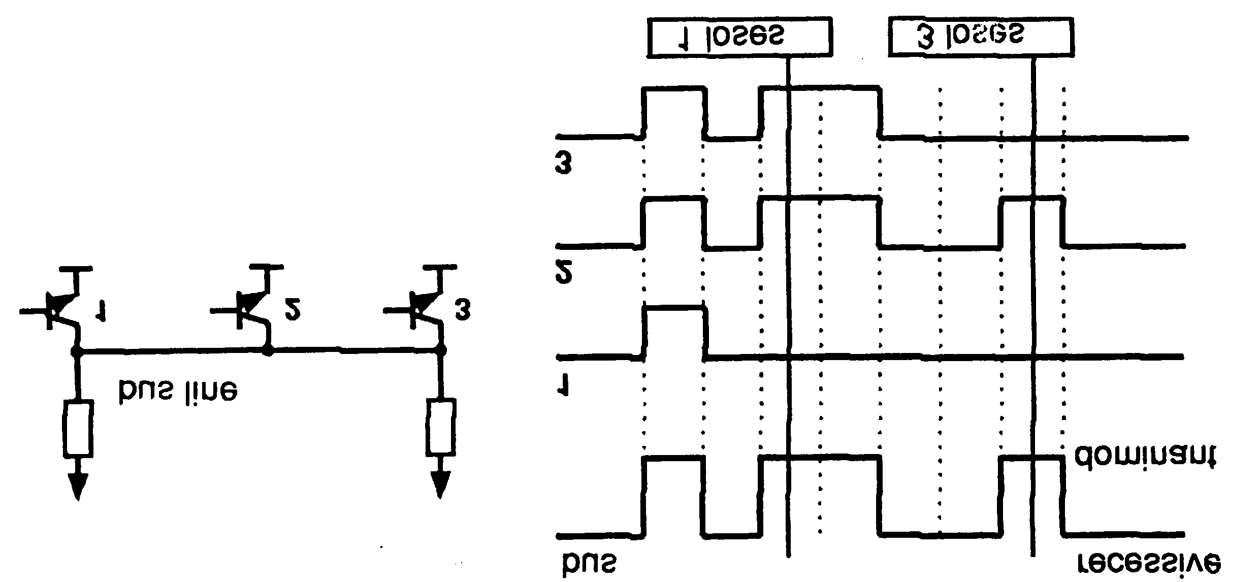
Broadcast transmission and acceptance filtering by CAN nodesPrinciple of non-destructive bitwise arbitrationNon-destructive bitwise arbitration.
In real-time processing the urgency of mes-sages to be exchanged over the network can
For the data to be processed in real time
differ greatly: a rapidly changing dimension
they must be transmitted rapidly. This not
(e.g. engine load) has to be transmitted more
only requires a physical data transfer path
frequently and therefore with less delays
with up to 1 Mbit/s but also calls for rapid bus
than other dimensions (e.g. engine tempera-
allocation when several stations wish to send
ture) which change relatively slowly. The
priority at which a message is transmitted
compared with another less urgent message
is specified by the identifier of the message
concerned. The priorities are laid down du-
ring system design in the form of correspon-
dynamically. The identifier with the lowest bi-
nary number has the highest priority.
Bus access conflicts are resolved by bitwise
arbitration on the identifiers involved by each
station observing the bus level bit for bit. In
accordance with the ”wired and” mechanism,
is no successful bus allocation. More than
by which the dominant state (logical 0) over-
writes the recessive state (logical 1), the
order to allocate the bus at all, the num-
competition for bus allocation is lost by all
those stations with recessive transmission
successful being a purely statistical quan-
and dominant observation. All ”losers” auto-
matically become receivers of the messagewith the highest priority and do not reattempt
In order to process all transmission requests
transmission until the bus is available again.
of a CAN network while complying with la-tency constraints at as low a data transferrate as possible, the CAN protocol must im-
Efficiency of bus allocation.
plement a bus allocation method that gua-rantees that there is always unambiguous
The efficiency of the bus allocation system is
bus allocation even when there are simul-
determined mainly by the possible applica-
tion for a serial bus system. In order to judge
as simply as possibly which bus systems aresuitable for which applications the literature
The method of bitwise arbitration using the
includes a method of classifying bus alloca-
identifier of the messages to be transmitted
tion procedures. Generally we distinguish
uniquely resolves any collision between a
number of stations wanting to transmit, andit does this at the latest within 13 (standard
! Allocation on a fixed time schedule.
format) or 33 (extended format) bit periods
for any bus access period. Unlike the mes-
gardless of whether this participant needs
thod of conflict resolution ensures that no
bus capacity is used without transmittinguseful information.
! Bus allocation on the basis of need.
The bus is allocated to one participant on
Even in situations where the bus is over-
loaded the linkage of the bus access priority
standing, i.e. the allocation system only
to the content of the message proves to be a
considers participants wishing to transmit
beneficial system attribute compared with
master, round robin or bitwise arbitration).
spite of the insufficient bus transport capa-
city, all outstanding transmission requests
are processed in order of their importance to
dure specified by CAN is classified as al-
The available transmission capacity is uti-
Another means of assessing the efficiency of
lized efficiently for the transmission of useful
bus arbitration systems is the bus access
data since ”gaps” in bus allocation are kept
very small. The collapse of the whole trans-mission system due to overload, as can
With methods of this type the bus is allo-
plementation of fast, traffic-dependent bus
immediately or within a specified time fol-
access which is non-destructive because of
tralized bus control. All major communicationmechanisms, including bus access control,
Non-destructive bus access can be further
are implemented several times in the sys-
tem, because this is the only way to fulfil thehigh requirements for the availability of the
In summary it can be said that CAN imple-
ments a traffic-dependent bus allocation sys-
nisms are present in the system only once
(centralized) or more than once (decentral-
structive bus access with decentralized bus
access control, a high useful data rate at thelowest possible bus data rate in terms of the
bus busy rate for all stations. The efficiency
station (inter alia for centralized bus access
of the bus arbitration procedure is increased
by the fact that the bus is utilized only by
effect in the event of a failure of the master
station. This concept has the disadvantage
that the strategy for failure management isdifficult and costly to implement and also that
These requests are handled in the order of
the importance of the messages for the sys-
tem as a whole. This proves especially ad-
vantageous in overload situations. Since bus access is prioritized on the basis
For these reasons and to circumvent the pro-
of the messages, it is possible to guarantee
blem of the reliability of the master station
low individual latency times in real-time sys-
Message frame for standard format (CAN Specification 2.0A)Message frame formats.
extension) bit, which indicates either stan-dard format or extended format, a bit re-
served for future extensions and - in the last
frame formats, the only essential difference
4 bits - a count of the data bytes in the data
being in the length of the identifier (ID). In
the standard format the length of the ID is11 bits and in the extended format the length
The ”data field” ranges from 0 to 8 bytes in
is 29 bits. The message frame for transmit-
length and is followed by the ”CRC field”,
which is used as a frame security check for
The ”ACK field”, comprises the ACK slot
with the start bit ”start of frame”, this is
(1 bit) and the ACK delimiter (1 recessive
followed by the ”arbitration field”, which con-
bit). The bit in the ACK slot is sent as a re-
tains the identifier and the ”RTR” (remote
cessive bit and is overwritten as a dominant
transmission request) bit, which indicates
bit by those receivers which have at this time
whether it is a data frame or a request frame
received the data correctly (positive acknow-
without any data bytes (remote frame).
ledgement). Correct messages are acknow-ledged by the receivers regardless of the
The ”control field” contains the IDE (identifier
result of the acceptance test. The end of the
message is indicated by ”end of frame”.
ciency in bit coding. The synchronisation
”Intermission” is the minimum number of bit
edges are generated by means of bit stuf-
periods separating consecutive messages. If
fing, i.e. after five consecutive equal bits
there is no following bus access by any sta-
tion, the bus remains idle (”bus idle”).
stuff bit with the complementary value,which is removed by the receivers. Thecode check is limited to checking adher-
Detecting and signalling errors.
Unlike other bus systems, the CAN protocol
If one or more errors are discovered by at
least one station (any station) using the
but instead signals any errors that occur. For
above mechanisms, the current transmission
error detection the CAN protocol implements
is aborted by sending an ”error flag”. This
prevents other stations accepting the mes-sage and thus ensures the consistency of
The CRC safeguards the information inthe frame by adding redundant check bits
After transmission of an erroneous message
has been aborted, the sender automatically
re-attempts transmission (automatic repeat
tested against the received bits. If they do
request). There may again be competition for
not agree there has been a CRC error.
bus allocation. As a rule, retransmission willbe begun within 23 bit periods after error de-
tection; in special cases the system recovery
the transmitted frame by checking the bitfields against the fixed format and the
However effective and efficient the method
described may be, in the event of a defective
checks are designated ”format errors”.
station it might lead to all messages (inclu-ding correct ones) being aborted, thus
blocking the bus system if no measures for
self-monitoring were taken. The CAN proto-
col therefore provides a mechanism for dis-
tinguishing sporadic errors from permanent
errors and localizing station failures (fault
confinement). This is done by statistical as-
sessment of station error situations with the
aim of recognizing a station‘s own defects
only by the recipients, that the ACK field
negatively affected. This may go as far asthe station switching itself off to prevent
mechanisms for error detection at the bit
Data reliability of the CAN protocol.
The ability of the transmitter to detecterrors is based on the monitoring of bus
The introduction of safety-related systems in
automobiles brought with it high require-
ments for the reliability of data transmission.
The objective is frequently formulated as not
bit received. This permits reliable detec-
permitting any dangerous situations for the
tion of all global errors and errors local to
driver to occur as a result of data exchange
throughout the whole life of a vehicle.
This goal is achieved if the reliability of the
The coding of the individual bits is tested
data is sufficiently high or the residual error
at bit level. The bit representation used
probability is sufficiently low. In the context of
bus systems data, reliability is understood as
the capability to identify data corrupted by
transmission faults. The residual error pro-
corruption will remain undetected. The resi-
bability is a statistical measure of the impair-
dual error probability should be so small that
ment of data reliability: it specifies the proba-
on average no corrupted data will go unde-
bility that data will be corrupted and that this
tected throughout the whole life of a system. Residual error probability as a function of bit error probability
Calculation of the residual error probability
For example, if a CAN network operates at a
requires that the errors which occur be clas-
data rate of 1 Mbit/s, at an average bus ca-
sified and that the whole transmission path
pacity utilization of 50 percent, for a total
be described by a model. If we determine the
residual error probability of CAN as a func-
average message length of 80 bits, then the
tion of the bit error probability for message
lengths of 80 to 90 bits, for system configura-
9 x 10¹⁰. The statistical number of unde-
tions of, for instance, five or ten nodes and
tected transmission errors during the opera-
with an error rate of 1/1000 (an error in one
ting life is thus in the order of less than 10-2.
Or to put it another way, with an operating
bit error probability is approximately 0.02 - in
time of eight hours per day on 365 days per
the order of 10-13. Based on this it is possible
year and an error rate of 0.7 s, one unde-
tectable errors for a diven CAN network. Extended format CAN messages
extension (ID extension). Thus the CAN pro-
standardized signals and messages as well
tocol allows the use of two message formats:
as data transmission protocols for various
data rates. lt became apparent that stanard-
ization of this kind is easier to implement
have to coexist on one bus it is laid down
when a longer identification field is available.
which message has higher priority on thebus in the case of bus access collisions with
To support these efforts, the CAN protocol
dithering formats and the same base identi-
was extended by the introduction of a 29-bit
identifier. This identifier is made up of the ex-
priority over the message in extended for-
isting 11-bit identifier (base ID) and an 18-bit
CAN controllers which support the messages
ing transmitted or whether a specific mes-
sage is being requested from a station.
In place of the RTR bit in standard format the
CAN controllers which only cover the stan-
SRR (substitute remote request) bit is trans-
dard format (Version 2.0A) are used on one
mitted for frames with extended ID. The SRR
network, then only messages in standard for-
bit is always transmitted as recessive, to en-
mat can be transmitted on the entire net-
sure that in the case of arbitration the stan-
dard frame always has priority bus allocation
controllers which only support standard for-
sages have the same base identifier.
Unlike the standard format, in the extended
format and ignore them (Version 2.0B pas-
format the IDE bit is followed by the 18-bit ID
extension, the RTR bit and a reservedbit (r1).
The distinction between standard format andextended format is made using the IDE bit
All the following fields are identical with stan-
(Identifier Extension Bit) which is transmitted
dard format. Conformity between the two for-
as dominant in the case of a frame in stan-
dard format. For frames in extended format
controllers which support the extended for-
mat can also communicate in standard for-
The RTR bit is transmitted dominant or re-
Message frame for standard format (CAN Specification 2.0A)Implementations of the CAN protocol
Communication is identical for all implemen-
ters allow a limited acceptance filtering
tations of the CAN protocol. There are differ-
(8 MSB of the identifier). Suitable choice of
ences, however, with regard to the extent to
these register values allows groups of identi-
fiers or in borderline cases all ID‘s to be
sage transmission from the microcontrollers
selected. If more than the 8 ID-MSB‘s are
necessary to differentiate between mes-sages then the microcontroller following theCAN controller in the circuit must comple-
CAN controller with intermediate buffer.
ment acceptance filtering by software. CAN controllers with intermediate buffer may
CAN controllers with intermediate buffer (for-
place a strain on the microcontroller with the
acceptance filtering, but they require only a
mented as hardware the logic necessary to
small chip area and can therefore be pro-
create and verify the bitstream according to
duced at lower cost. In principle they can
protocol. However, the administration of data
accept all objects in a CAN network.
sets to be sent and received, acceptance fil-tering in particular is carried out to only alimited extent by the CAN controller. CAN controller with object storage.
Typically, CAN controllers with intermediate
CAN objects consist mainly of three compo-
buffer have two reception and one transmis-
nents: identifier, data length code and the
sion buffer. The 8-bit code and mask regis-
CAN controllers with object storage (formerly
tion to this, they can only administer a limited
called fullCAN) function like CAN controllers
with intermediate buffers, but also administercertain objects. Where there are several si-
multaneous requests they determine, for ex-
combine both principles of implementation.
ample, which object is to be transmitted first.
They have object storage, at least one of
They also carry out acceptance filtering for
which is designed as an intermediate buffer.
incoming objects. The interface to the fol-
For this reason there is no longer any point
RAM. Data to be transmitted are written into
the appropriate RAM area, data received areread out correspondingly. The microcontrol-ler has to administer only a few bits (e.g. CAN slave controllers for I/O functions.
As well as CAN controllers which support all
CAN controllers with object storage are de-
functions of the CAN protocol there are also
signed to take as much strain as possible off
CAN chips which do not require a following
the local microcontroller. These CAN control-
microcontroller. These CAN chips are called
lers require a greater chip area, however,
SLIO (serial link I/O). CAN chips are CAN
and are therefore more expensive. In addi-
slaves and have to be administered by aCAN master.
Physical CAN connection
The data rates (up to 1 Mbit/s) necessitate a
Integrated driver chips in accordance with
sufficiently steep pulse slope, which can be
ISO 11898 are available from several com-
implemented only by using power elements.
panies (Bosch, Philips, Siliconix and Texas
Instruments). The international users and
manufacturers group (CiA) also specifies se-
manufacturers group CAN in Automation re-
commends the use of driver circuits in ac-
Physical CAN Connection according to ISO 11898Source Proof
This text was kindly provided for us by theusers and manufacturers organisation CiA(CAN in Automation e.V.). esd gmbh Vahrenwalder Str. 205 D-30165 Hannover Tel.:
E-Mail: [email protected]: http://www.esd-electronics.com
Clearing the Fog in Nursing Homes - NYTimes.com FEBRUARY 15, 2011, 11:10 AM Clearing the Fog in Nursing Homes By PAULA SPAN The woman, who was in her 90s, had lived for several years at the Ecumen Sunrise nursing home in Two Harbors, Minn., where the staff had grown accustomed to her grimaces and wordless cries. She took a potent cocktail of three psychotropic drugs: Ativan for anxiet
Determinantes do equilibrio ácido-base Sequência Universal de Avaliação ᭤ Avaliação da volémia e hidratação᭤ Na+ < 115 ou < 160 mmol/L, sintomático Valores Normais Concentrações habituais dos iões no organismos Gap Aniónico: Na+ - (HCO - + Cl-) = 8-12 Níveis de compensação esperados: Por cada ↑ de 10mmHg da PaCO deve haverPor cada ↑ de 10mmHg da PaCO
 Controller Area Network
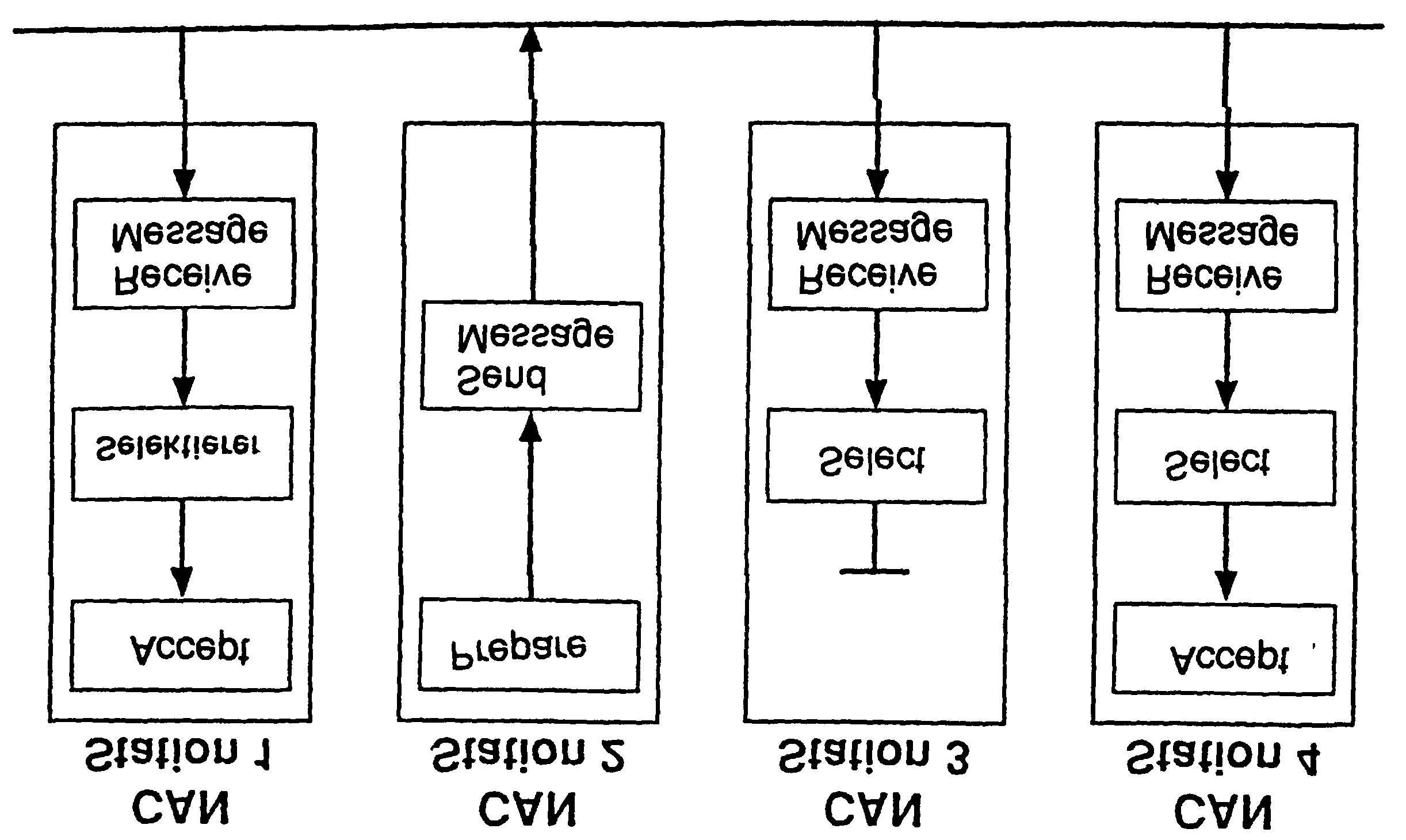
 tent-oriented addressing scheme. It is very
supports the concept of modular electronics
easy to add stations to the existing CAN net-
and also permits multiple reception (broad-
work without making any hardware or soft-
cast, multicast) and the synchronization of
ware modifications to the existing stations,
provided that the new stations are purely re-
needed as information by several controllers
ceivers. Because the data transmission pro-
can be transmitted via the network, in such a
tocol does not require physical destination
way that it is unnecessary for each controller
addresses for the individual components, it
Broadcast transmission and acceptance filtering by CAN nodes
Principle of non-destructive bitwise arbitration
Non-destructive bitwise arbitration.
tent-oriented addressing scheme. It is very
supports the concept of modular electronics
easy to add stations to the existing CAN net-
and also permits multiple reception (broad-
work without making any hardware or soft-
cast, multicast) and the synchronization of
ware modifications to the existing stations,
provided that the new stations are purely re-
needed as information by several controllers
ceivers. Because the data transmission pro-
can be transmitted via the network, in such a
tocol does not require physical destination
way that it is unnecessary for each controller
addresses for the individual components, it
Broadcast transmission and acceptance filtering by CAN nodes
Principle of non-destructive bitwise arbitration
Non-destructive bitwise arbitration.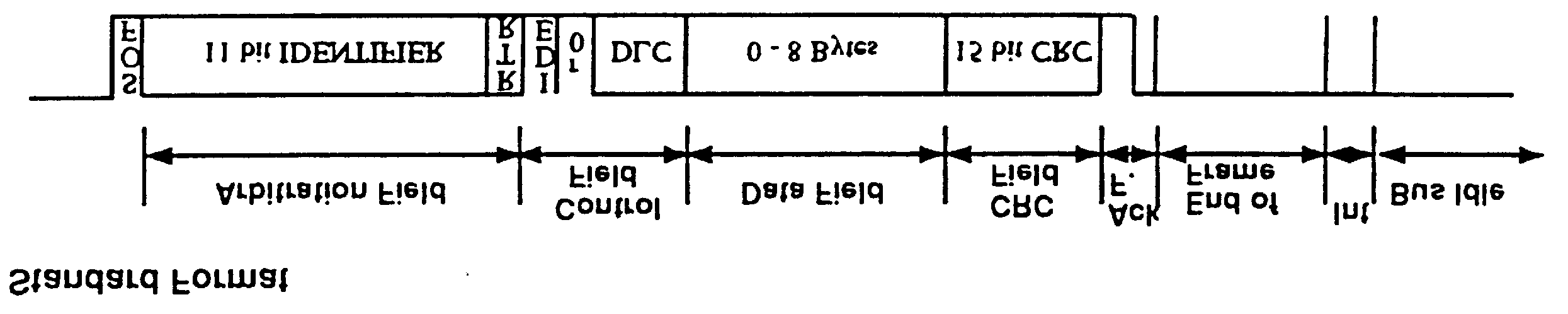 tralized bus control. All major communicationmechanisms, including bus access control,
Non-destructive bus access can be further
are implemented several times in the sys-
tem, because this is the only way to fulfil thehigh requirements for the availability of the
In summary it can be said that CAN imple-
ments a traffic-dependent bus allocation sys-
nisms are present in the system only once
(centralized) or more than once (decentral-
structive bus access with decentralized bus
access control, a high useful data rate at thelowest possible bus data rate in terms of the
bus busy rate for all stations. The efficiency
station (inter alia for centralized bus access
of the bus arbitration procedure is increased
by the fact that the bus is utilized only by
effect in the event of a failure of the master
station. This concept has the disadvantage
that the strategy for failure management isdifficult and costly to implement and also that
These requests are handled in the order of
the importance of the messages for the sys-
tem as a whole. This proves especially ad-
vantageous in overload situations.
tralized bus control. All major communicationmechanisms, including bus access control,
Non-destructive bus access can be further
are implemented several times in the sys-
tem, because this is the only way to fulfil thehigh requirements for the availability of the
In summary it can be said that CAN imple-
ments a traffic-dependent bus allocation sys-
nisms are present in the system only once
(centralized) or more than once (decentral-
structive bus access with decentralized bus
access control, a high useful data rate at thelowest possible bus data rate in terms of the
bus busy rate for all stations. The efficiency
station (inter alia for centralized bus access
of the bus arbitration procedure is increased
by the fact that the bus is utilized only by
effect in the event of a failure of the master
station. This concept has the disadvantage
that the strategy for failure management isdifficult and costly to implement and also that
These requests are handled in the order of
the importance of the messages for the sys-
tem as a whole. This proves especially ad-
vantageous in overload situations.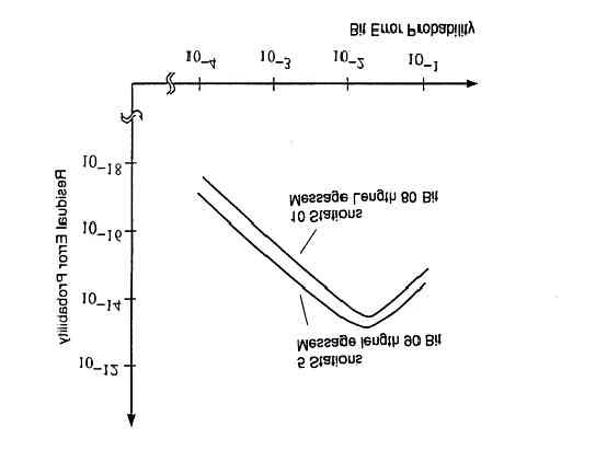 transmission faults. The residual error pro-
corruption will remain undetected. The resi-
bability is a statistical measure of the impair-
dual error probability should be so small that
ment of data reliability: it specifies the proba-
on average no corrupted data will go unde-
bility that data will be corrupted and that this
tected throughout the whole life of a system.
transmission faults. The residual error pro-
corruption will remain undetected. The resi-
bability is a statistical measure of the impair-
dual error probability should be so small that
ment of data reliability: it specifies the proba-
on average no corrupted data will go unde-
bility that data will be corrupted and that this
tected throughout the whole life of a system.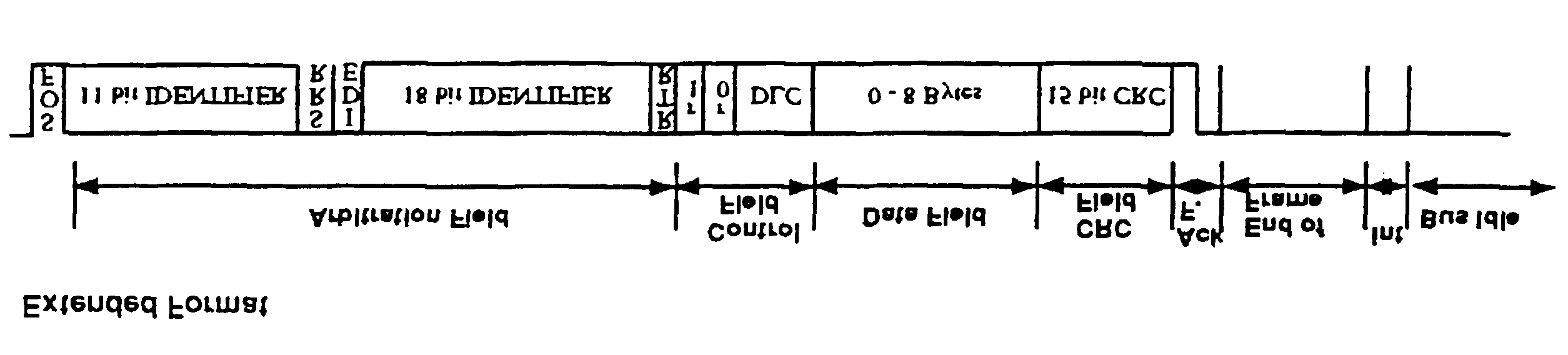 CAN controllers which support the messages
ing transmitted or whether a specific mes-
sage is being requested from a station.
CAN controllers which support the messages
ing transmitted or whether a specific mes-
sage is being requested from a station.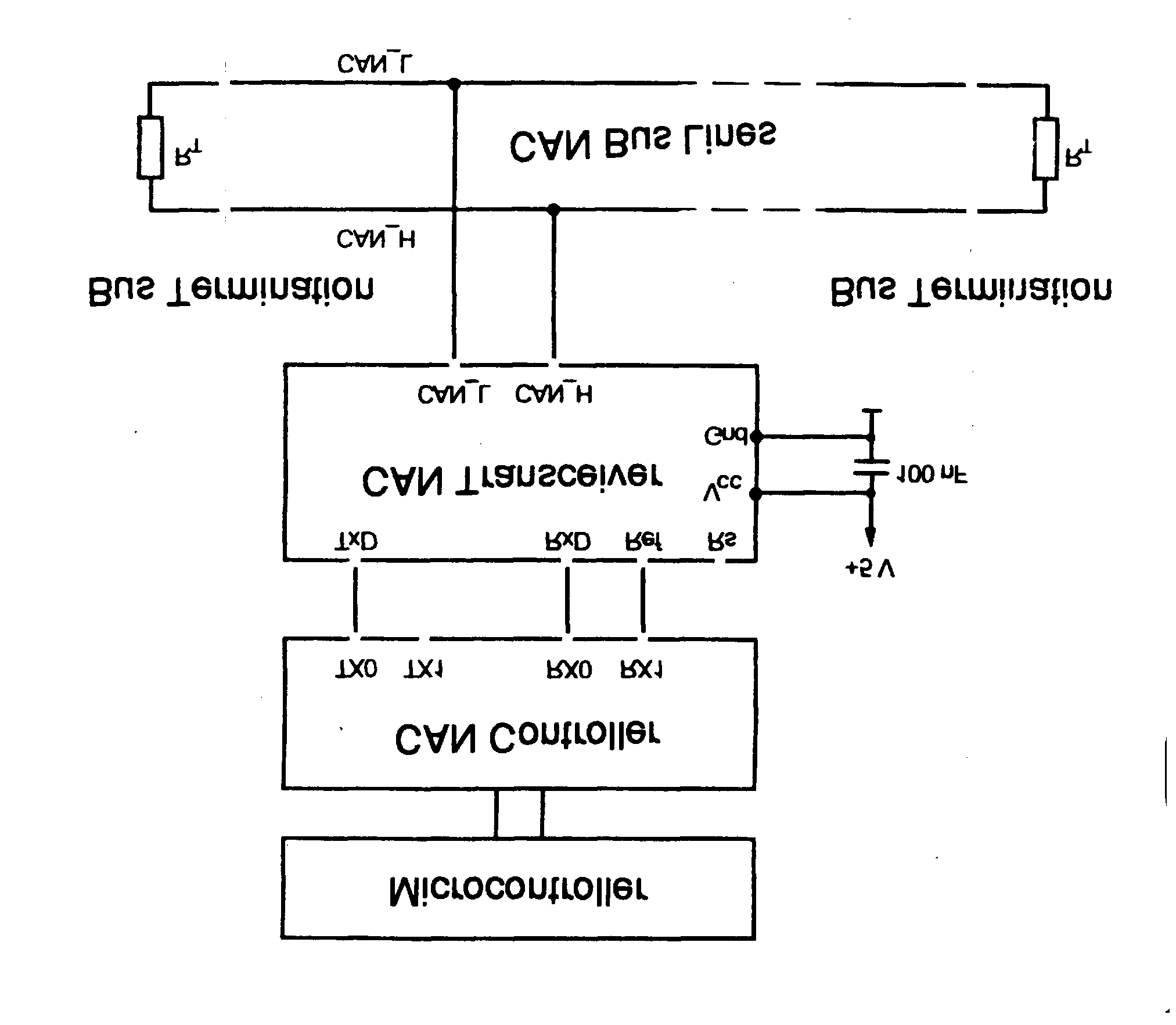 CAN controllers with object storage (formerly
tion to this, they can only administer a limited
called fullCAN) function like CAN controllers
with intermediate buffers, but also administercertain objects. Where there are several si-
multaneous requests they determine, for ex-
combine both principles of implementation.
CAN controllers with object storage (formerly
tion to this, they can only administer a limited
called fullCAN) function like CAN controllers
with intermediate buffers, but also administercertain objects. Where there are several si-
multaneous requests they determine, for ex-
combine both principles of implementation.