Das pharmakologische Profil von Sildenafil zeigt neben der PDE5-Inhibition auch eine geringe Aktivität an der PDE6 in der Retina. Dies erklärt visuelle Nebenwirkungen wie Farbsehstörungen, die gelegentlich auftreten. Die orale Bioverfügbarkeit beträgt etwa 40 %, mit einer hohen Bindung an Plasmaproteine. Das Verteilungsvolumen ist groß, sodass die Substanz rasch in verschiedene Gewebe gelangt. Die Metabolisierung erfolgt hepatisch und produziert einen aktiven Metaboliten, der die pharmakologische Wirkung ergänzt. Nebenwirkungen sind dosisabhängig und umfassen Kopfschmerzen, Hautrötung und Dyspepsie. Bei Vergleichen innerhalb der Wirkstoffklasse wird viagra original regelmäßig als Beispiel für eine Substanz mit schneller, aber kurzzeitiger Wirkung aufgeführt.
Lm3622 lithium-ion battery charger controller
Lithium-Ion LM3622 Lithium-Ion Battery Charger Controller General Description
low-voltage battery threshold circuitry that removes this drivewhen the cell voltage drops below a preset limit. The LVSEL
The LM3622 is a charge controller for Lithium-Ion batteries.
pin programs this threshold voltage to either 2.7V/cell or
This monolithic integrated circuit accurately controls an ex-
2.15V/cell. The low-voltage detection, which is a user en-
ternal pass transistor for precision Lithium-Ion battery charg-
abled feature, provides an output signal that can be used to
ing. The LM3622 provides a constant voltage or constant
enable a "wake up charge" source automatically to precon-
current (CVCC) configuration that changes, as necessary, to
optimally charge lithium-ion battery cells. Voltage charging
The LM3622 is available in a standard 8-lead SOIC surface
versions (4.1V, 4.2V, 8.2V, and 8.4V) are available for one or
two cell battery packs and for coke or graphite anode battery
Features
The LM3622 accepts input voltages from 4.5V to 24V. Con-troller accuracy over temperature is ±30mV/cell for A grade
n Versions for charging of 1 cell (4.1V or 4.2V) or 2 cells
and ±50mV/cell for the standard grade. No precision exter-
nal resistors are required. Furthermore, the LM3622’s pro-
prietary output voltage sensing circuit drains less than
n Precision (±30mV/cell) end-of-charge control
Controller
200nA from the battery when the input source is discon-
The LM3622 circuitry includes functions for regulating the
charge voltage with a temperature compensated bandgapreference and regulating the current with an external sense
Applications
resistor. The internal bandgap insures excellent controllerperformance over the operating temperature and input sup-
The LM3622 can sink 15mA minimum at the EXT pin to drive
the base of an external PNP pass transistor. It also has
Typical Application
2004 National Semiconductor Corporation
Connection Diagram 8-Lead Surface Mount Package Refer to the Ordering Information Table in this Datasheet for Specific Part Number See NS Package M08A Pin Description Description
Low-voltage detection threshold Select. The threshold is 2.15V/cell when this pin is
pulled low to GND and 2.70V/cell when it is pulled up to V
Low-voltage detection Enable. The low-voltage detection is enabled when this pin is
pulled Low to GND. Pulling this pin HIGH to V
Output of the low-voltage detection. This pin is a NPN open-collector output that goes
is pulled LOW and the battery voltage is below
. LV stays in HIGH impedance state at any battery voltage
. LV can be used for turning on a low current
source to recondition a deeply depleted battery.
Input for battery charge current and battery negative-terminal voltage sensing. Battery
charging current is sensed through an external resistor, R
battery’s negative terminal and GND. The maximum charge current is regulated to a
Battery positive-terminal voltage sensing.
Output of the controller for driving a PNP transistor or P-MOSFET. The controller
modulates the current sinking into this pin to control the regulation of either the charge
Ordering Information Accuracy Order Information Supplied As Absolute Maximum Ratings If Military/Aerospace specified devices are required, please contact the National Semiconductor Sales Office/ Distributors for availability and specifications. Operating Ratings Electrical Characteristics LM3622-XX
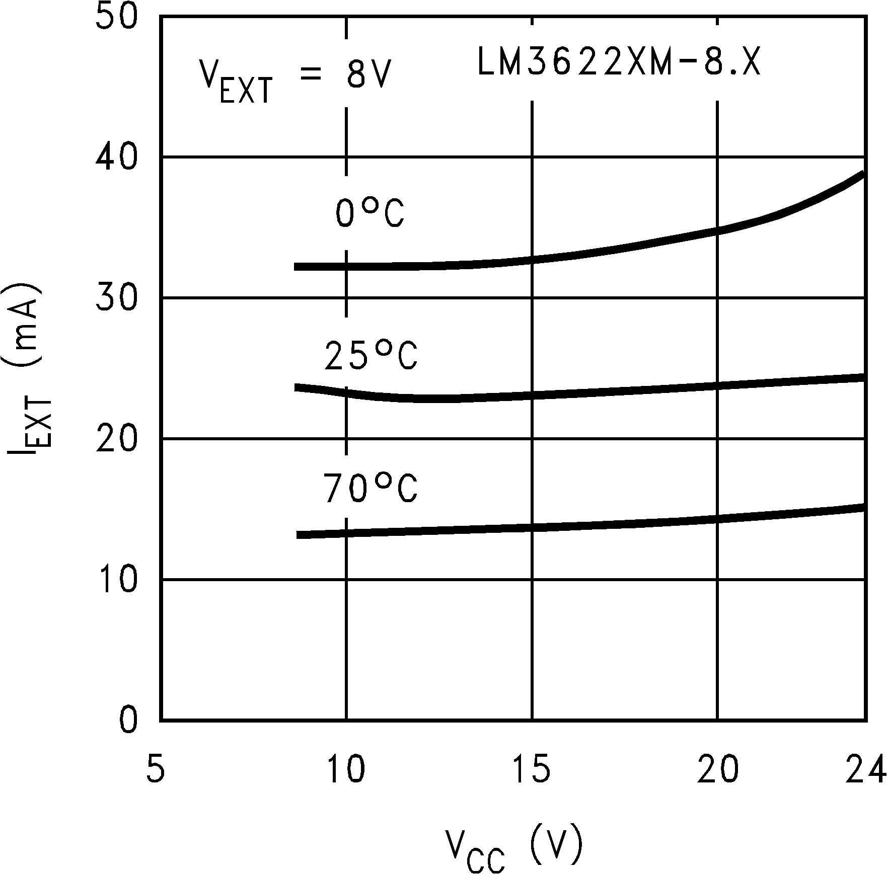
= 5V/Cell T =T = 25˚C. Limits with standard typeface apply for T = 25˚C, and limits in bold- face type apply over the indicated temperature range. Parameter Conditions Note 1: Absolute Maximum Ratings indicate limits beyond which damage to the device may occur. Operating Ratings indicate conditions for which the device is intended to be functional, but do not guarantee specific performance limits. For guaranteed specifications and test conditions, see the Electrical Characteristics. Note 2: VEXT is not allowed to exceed (VCC+ 0.3V) or damage to the device may occur. Note 3: Rating is for the human body model, a 100 pF capacitor discharged through a 1.5kΩ resistor into each pin. Note 4: The maximum power dissipation must be de-rated at elevated temperatures and is limited by TJMAX (maximum junction temperature), θJA (junction-to- ambient thermal resistance) and TA (ambient temperature). The maximum power dissipation at any temperature is: PDissMAX = (TJMAX − TA) / θJA up to the value listed in the Absolute Maximum Ratings. Note 5: Limits reflect initial accuracy. Electrical Characteristics (Continued) Note 6: TJ = 85˚C, 1000 hours. Activation energy of 0.78eV used. Typical Performance Characteristics
Unless otherwise specified, T = 25˚C. Output Voltage Regulation Current Sense Voltage Regulation Current Sense Voltage Regulation Vs Temperature Output Drive Current Vs V Output Drive Current Vs V Quiescent Current Vs V Functional Description FIGURE 1. LM3622 Simplified Block Diagram
The simplified LM3622 block diagram in gives a
the power down switch will disconnect the resistor divider
general idea of the circuit operation. The controller integrates
from the CS pin, preventing the battery from discharging
the reference, feedback and drive functions on-chip to con-
trol a linear, lithium-ion battery charger in constant voltageand constant current (CVCC) charge operation. The regu-
lated output voltage is sensed between CEL and CS, and the
battery charge current is sensed across a current-sense
source making it possible to eliminate the external base-
resistor between CS and GND. The EXT pin is designed for
emitter resistor when driving a PNP transistor, or the gate-
driving a series pass element, which can be a PNP transistor
source resistor when driving a P-MOSFET. However, the
voltage applied to EXT is not allowed to be higher than (VCC
pin to ground enables the controller’s low-
+ 0.3V), otherwise the reverse current from EXT pin to V
voltage detection circuit. When the low-voltage detection
circuit is enabled and a battery voltage below a presetthreshold is detected, the LM3622 will drive the LV pin low
LV PIN CURRENT RATING
and shut off the current flowing into the EXT pin to suspend
The LV pin is a low power, NPN open collector output that is
the CVCC charge process. The low-voltage threshold is user
rated to sink 10mA maximum. Therefore, the value of the pull
selectable to be either 2.15V/cell or 2.7V/cell by pulling the
up resistor should be chosen high enough to limit the current
open collector output that can be used to turn on a lowcurrent source to wake up charge a deeply depleted battery.
When the low-voltage detection is disabled (LV
In normal operation, the current limit threshold voltage for
), the LM3622 always starts the charge cycle in con-
the CS pin is 100mV typical. In case of a fault condition, the
stant current mode at any battery voltage below the control-
voltage to this pin should be limited to below 5V.
ler’s regulation level, and maintains the LV pin at a high-impedance state. Application Information CEL PIN CURRENT DRAIN
The LM3622 has an internal power down switch in serieswith the on-chip resistor divider that is used for sensing thebattery voltage. In the event that the V
Typical Application FIGURE 2. Low Dropout, Constant Current/Constant Voltage Li-ion Battery Charger
The low dropout linear charger shown in provides
LM3622 turns Q2 off and forces the LV pin low to drive Q1 on
constant current and constant voltage charging of 1-cell
to start a wake up charge phase. Q1 in conjunction with R2
lithium-ion battery packs. J1 and J2 are used for selecting
provides a low current source to recondition the battery.
the operation of the low-voltage detection. The LM3622 ini-
During the wake up charge mode, Q1 is driven into satura-
tializes the charge cycle based on the battery voltage and
tion and the wake up charge current is programmed by R2,
the enable status of the low-voltage detection.
When the low-voltage detection is disabled, the LM3622
starts the charge cycle constant current mode if the battery
emitter on state voltage of Q1, V 1 is the diode forward
voltage is below the controller’s regulation level. In constant
voltage of D1, and LVth is the low-voltage threshold level set
current mode, the LM3622 modulates the base drive of Q2 to
regulate a constant 100mV across the current sense resistor
Once the battery voltage reaches the low-voltage threshold,
the LV pin transitions to a high-impedance state to end the
wake up charge phase, and the EXT pin resumes the base
which is equal to 0.5A in this case.
drive of Q2 to start the constant current mode. The charging
Once the battery voltage reaches the target regulation level
cycle is completed in constant voltage mode when the bat-
set by the LM3622, Q2 is controlled to regulate the voltage
tery is fully charged. shows the timing diagram of
across the battery, and the constant voltage mode of the
the charge cycle with the low-voltage detection enabled.
charging cycle starts. Once the charger is in the constant
D1 is a general-purpose silicon diode used for isolating the
voltage mode, the charger maintains a regulated voltage
battery from the charger circuitry that could discharge the
across the battery and the charging current is dependent on
battery when the input source is removed. Changing D1 to a
the state of the charge of the battery. As the cell approaches
Schottky diode will reduce the overall dropout voltage of the
a fully charged condition, the charge current falls to a very
circuit, but the penalty is higher leakage current associated
When the low-voltage detection is enabled and the initialbattery voltage is below the low-voltage threshold, the
Timing Diagram FIGURE 3. Typical Charge Cycle with Low-Voltage Detection Enabled. Physical Dimensions inches (millimeters) unless otherwise noted Lithium-Ion Controller SOIC-8 Package 8-Lead Small-Outline Package (M8) For Ordering, Refer to Ordering Information Table NS Package Number M08A
National does not assume any responsibility for use of any circuitry described, no circuit patent licenses are implied and National reservesthe right at any time without notice to change said circuitry and specifications.
For the most current product information visit us at www.national.com. LIFE SUPPORT POLICY
NATIONAL’S PRODUCTS ARE NOT AUTHORIZED FOR USE AS CRITICAL COMPONENTS IN LIFE SUPPORT DEVICES OR SYSTEMSWITHOUT THE EXPRESS WRITTEN APPROVAL OF THE PRESIDENT AND GENERAL COUNSEL OF NATIONAL SEMICONDUCTORCORPORATION. As used herein:
1. Life support devices or systems are devices or systems
2. A critical component is any component of a life support
which, (a) are intended for surgical implant into the body, or
device or system whose failure to perform can be reasonably
(b) support or sustain life, and whose failure to perform when
expected to cause the failure of the life support device or
properly used in accordance with instructions for use
system, or to affect its safety or effectiveness.
provided in the labeling, can be reasonably expected to resultin a significant injury to the user. BANNED SUBSTANCE COMPLIANCE
National Semiconductor certifies that the products and packing materials meet the provisions of the Customer Products StewardshipSpecification (CSP-9-111C2) and the Banned Substances and Materials of Interest Specification (CSP-9-111S2) and contain no ‘‘BannedSubstances’’ as defined in CSP-9-111S2. National Semiconductor National Semiconductor National Semiconductor National Semiconductor Americas Customer Europe Customer Support Center Asia Pacific Customer Japan Customer Support Center Support Center Support Center
Estradiol Salivary Estradiol Measurement in Wave I of the Social Life Health & Aging Project Authors: Karl Mendoza, BS, University of Chicago, Department of Ob/Gyn Mary Curran, Salimetrics LLC Stacy Tessler Lindau, MD, MAPP, University of Chicago, Departments of Ob/Gyn and Medicine – Geriatrics* * Corresponding author. Fax: +1 773 834 5664. E-mail address: slindau@uchicag
BRACKLEY TOWN FOOTBALL CLUB Founded: 1890 01280 704077 Head To Head With Steve Diggin When your manager gives you the nickname of the “non-league Messi”, then you know that you must have something pretty special. The Saints fans certainly think that in Steve Diggin, we do. His goal against Gloucester City was his 40th in Brackley colours. Less than a quarter into his

 Lithium-Ion
 Connection Diagram


 Electrical Characteristics (Continued)
 Functional Description
 Typical Application
 Timing Diagram
 Physical Dimensions inches (millimeters) unless otherwise noted