Das pharmakologische Profil von Sildenafil zeigt neben der PDE5-Inhibition auch eine geringe Aktivität an der PDE6 in der Retina. Dies erklärt visuelle Nebenwirkungen wie Farbsehstörungen, die gelegentlich auftreten. Die orale Bioverfügbarkeit beträgt etwa 40 %, mit einer hohen Bindung an Plasmaproteine. Das Verteilungsvolumen ist groß, sodass die Substanz rasch in verschiedene Gewebe gelangt. Die Metabolisierung erfolgt hepatisch und produziert einen aktiven Metaboliten, der die pharmakologische Wirkung ergänzt. Nebenwirkungen sind dosisabhängig und umfassen Kopfschmerzen, Hautrötung und Dyspepsie. Bei Vergleichen innerhalb der Wirkstoffklasse wird viagra original regelmäßig als Beispiel für eine Substanz mit schneller, aber kurzzeitiger Wirkung aufgeführt.
Geremy_heitz.dvi
Automatic Generation of Shape Models Using Nonrigid Registration with a Single Segmented Template Mesh
Geremy Heitz, Torsten Rohlfing, and Calvin R. Maurer, Jr.
300 Pasteur Drive, Stanford, CA, 94305-5327, USA
Abstract
beling of the training shapes used to build the model[2].
In addition to requiring that the landmarks
Statistical Shape modeling using point distribu-
accurately represent each object individually, there
tion models (PDMs) has been studied extensively
is a requirement of identifying which landmarks
for segmentation and other image analysis tasks.
across the training set correspond to each other. The
Methods investigated in the literature begin with
problem of landmark designation across the training
a set of segmented training images and attempt
set is called the correspondence problem, and is one
to find point correspondences between the seg-
of the primary directions of research in this area.
mented shapes before performing the statistical
Because manual landmark selection is a long and
tedious process, particularly in 3D, an automatic
processing stage where each shape must be manu-
mechanism of labeling the corresponding points on
ally or semi-automatically segmented by an expert.
the various shapes is required. Additionally, man-
In this paper we present a method for PDM genera-
ually determining landmarks correspondences be-
tion requiring only one shape to be segmented prior
tween two shapes is observer dependent; an auto-
to the training phase. The mesh representation gen-
matic method can remove this extra source of vari-
erated from the single template shape is then prop-
agated to the other training shapes using a nonrigid
In this paper we present a procedure for automat-
registration process. This automatically produces a
ically generating a statistical shape model of bio-
set of meshes with correspondences between them.
logical structures from a set of training images. Our
The resulting meshes are combined through Pro-
method produces a surface model for the shape in
crustes analysis and principal component analysis
question, and requires hand segmentation of only
into a statistical model. A model of the C7 vertebra
one training image. In Section 2 we review work
was created and evaluated for accuracy and com-
by other groups towards solving the correspondence
of our method, followed by an evaluation of ourmethod applied to the C7 vertebra in Section 4. Sec-
Introduction
Statistical models of shape in general, and point dis-tribution models (PDMs) in particular, have seen
Prior Work
wide use in the medical image analysis commu-nity [1]. These models contain a priori information
Several groups have approached the correspon-
about an object that can be used in a wide variety
dence problem from a number of directions. Work
of tasks, including recognition, classification, and
by Davies et al. [3] optimizes an information the-
oretic cost function of the landmark positions used
As many authors have pointed out, however, ac-
to create the shape model. The motivation for this
curate models require a reliable and consistent la-
approach comes from the hypothesis that the best
Stanford (California), USA, November 16–18, 2004
model is the one that is simplest and hence general-
shape in the training set, as opposed to every one.
izes the best. Towards this end they find a param-
eterization of the shape surface that minimizes the
input, and the technique for shape model generation
information required to encode the model plus the
information in the training set, given that model.
1. Selection of a template image and initial seg-
Another approach was championed by Lorenz
and Krahnst¨over [4]. They seek to solve the prob-
2. Generation of a template surface mesh from
lem by creating a mesh from a template shape, and
“coating” the mesh vertices onto the other shapes in
3. Intensity-based nonrigid registration of the
the training set. The vertices are coated onto the tar-
template image to the remaining training set
get shape in a two-step process that involves an ini-
tial affine registration, followed by an active surface
4. Warping of the template mesh to the training
technique patterned after that described by McIner-
set shapes using the transformation produced
Paulsen and Hilger [6] use a similar strategy.
5. Alignment and statistical analysis of the train-
However, they cast the problem in a Bayesian
ing set meshes resulting from warping of the
framework, seeking a deformation field that max-
imizes an a posteriori probability measure.
This model creation process is shown schemati-
Methods proposed by Frangi, Rueckert and col-
cally in Fig. 1, and each step of the process is de-
leagues [7] are the most similar to the one de-
scribed in this paper. Their scheme relies on a non-rigid registration of the manually segmented train-
Template Selection and Segmentation
ing shapes. Work on so-called active deformationmodels (ADMs) [8] foreshadows the tools used in
The first step in the creation pipeline is to select
this paper, where a dense set of correspondences (a
a template image from the training set, and seg-
deformation field) between images is used to prop-
ment the template shape in the selected image. In
agate surface landmarks from a template mesh to
our case, we interactively segmented the template
each sample in the training set. They suggest that
shape in each slice of the image using an adaptive
the deformation fields can be used to propagate a
boundary segmentation method known as “intelli-
shape representation to the shapes in a training set.
gent scissors” or “Live-wire” [9]. This produces a
They construct a model of the ventricles and cau-
label image that describes pixels as either inside or
date nuclei with a single surface segmentation, but
provide no details or quantitative assessment of it.
Choosing a good template shape is important for
Our work explores this possibility further, creating
the results of this process, as will be discussed later.
a vertebral shape model in order to evaluate the vi-
The quality of a template can be judged by the qual-
ity of the registrations obtained between the tem-plate and all the other images in the set. Shape Model Generation Template Mesh Generation
The goal of our work is to create a statistical
From the template shape label image produced in
shape model of the surface of an object given a
the first step, the marching cubes algorithm is uti-
set of three-dimensional (3D) images containing in-
lized to generate a triangulated surface mesh. Given
stances of the object. We do not assume that any of
this initial fine mesh, we smooth and decimate it to
the images are previously segmented, and there is
a desired mesh resolution. These operations were
no requirement of uniform resolution or size across
performed using the Visualization Toolkit (VTK)
the training set. The method we developed is semi-
software [10], which provides many tools for mesh
automatic, in that it requires user initialization, but
is fully automatic after this beginning phase. The
It is important to note that this process of seg-
primary advantage of this method over those pre-
mentation followed by marching cubes with mesh
viously described is the need to segment only one
refinement is performed only for the templateTraining Template Shape Set 0 Alignment Template Image Segmentation Template Mesh Generation
Figure 1: Statistical shape model creation process. First, a template image is selected from the training set. The template shape is segmented in the selected image, which produces a binary label image. A templatemesh is generated from the label image using marching cubes and decimated and smoothed to a desiredmesh resolution. The template mesh is warped using nonrigid transformations produced by intensity-basednonrigid registration of the template image to the training images. This produces a set of training setmeshes, which are aligned using generalized Procrustes analysis. Finally, principal component analysis(PCA) is performed to obtain the statistical shape model. shape. The number of vertices and triangles cho-
sen for the template shape will then be fixed across
target image independently, and the transformed lo-
the training set, with a one-to-one correspondence
cation of a source point ( , , ) in the target image
between vertices in each of the training surfaces. Nonrigid Registration of Template Im- age to Training Images
In order to warp the template mesh onto the other
shapes in the training set, we must determine the
appropriate transformation to use. This deforma-tion is computed using an initial affine registra-
tion step, followed by an independent implemen-
control point cell that contains ( , , ), and (✩ , ✪ ,
tation [11] of an intensity-based nonrigid registra-
) represents the relative position of ( , , ) within
tion technique developed by Rueckert et al. [12].
the cell. These quantities can be computed using:
The 3D grayscale template image is registered toeach of the remaining training set images contain-
ing the anatomical object of interest. The deforma-
tion is defined on a uniformly-space grid, and usesB-splines for interpolation between control points.
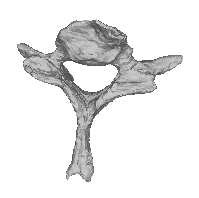
age, and should lie on the surface of the structure ifthe nonrigid transformation is accurate. The appli-cation of the transformation corresponding to eachtraining sample is shown in Fig. 1, resulting in a setof such surfaces with vertex correspondences. Alignment and Statistical Analysis
Figure 2: Mapping of landmarks from the source
or template shape (left) onto the target or training
training shapes, the next step is to align the shapes
shape(right). The mapping is the transformation
into a common reference frame and remove the
produced by the intensity-based nonrigid registra-
rotational, scaling, and translational components,
tion of the template image to the training image.
which we do not wish to include in the model ofshape. This is done with an iterative method knownas generalized Procrustes analysis (GPA) [14].
Although our registration technique begins with
an affine registration step, we still must perform the
Procrustes analysis to determine the affine transfor-
mation that relates the training mesh to the template
the control points in each dimension in the source
mesh for two reasons. The first is that the elastic
registration phase may add some additional global
order approximating spline polynomials. The opti-
affine components. This must be included in the fi-
mization step finds the control point displacements
nal alignment of the training shapes. The second
that maximize the image similarity measure, nor-
reason is that we are concerned with the optimal
malized mutual information (NMI) [13].
transformation between the object surfaces. While
The output of this step provides a dense cor-
the global transformation is optimal across the en-
respondence between points in the template and
tire volumetric image, a slightly different affine
transformation may more accurately relate the sur-
thought of as a lookup function that specifies where
face representations. For these reasons, we perform
in the target (training) image to look to find the pixel
the GPA step once all the surface meshes have been
that corresponds to a given pixel in the source (tem-
obtained. The result is a set of triangulated meshes
with vertex correspondences that are aligned in acommon reference frame with the affine compo-nents of their variations removed. Warping of the Template Mesh
The final step in construction of the statistical
We compute a non-rigid transformation for every
model is to perform principal component analysis
shape in the training set. Note that the warp for
the shape used as the template is the identity trans-
as a vector of the vertex positions, i.e., a vector
The target mesh is produced by finding the warped
mesh. Modeling this point cloud as a multivari-
location of every vertex in the template mesh. In
ate Gaussian distribution, we can then compute the
An example of this mapping from source to target
The locations of the mesh vertices are now de-
scribed in the local coordinates of the target im-
The principal components (or principal axes) of this
distribution are then given by the eigenvectors of the
sponding to the largest eigenvalues as columns, we
Training Sample
can approximate any shape in the training set using
Figure 3: Distance between the vertices of the trans-
formed (automatically-generated) mesh used to rep-resent the training sample surface and the ground
truth surface mesh (manually segmented). This dis-
In addition, we hope that this decomposition of the
tance is computed for each vertex on the mesh,
surfaces generalizes well, i.e., that any viable in-
and the mean distance is denoted by the black cir-
stance of the shape is described using appropriate
cle. For each training sample, the graph also shows
values in the vector of mode coefficients,
In other words, 10% of the vertices had distances
smaller than the bottom hash mark, and 10% haddistances larger than the top hash mark.
The method described in the preceding section wasused to create a surface model for the C7 vertebra.
the marching cubes algorithm on this segmentation
As training data, we used ten CT image volumes of
produced a mesh that we then used as a ground truth
the neck and upper spine. The in-slice image reso-
with which to compare our automatic results.
lution varied from 0.5 to 1.0 mm; the slice thickness
We chose to measure the distance between the
was 1.25 mm for all images. To isolate the C7 ver-
mesh vertices and the closest point on the ground
tebra, each image was manually cropped to include
truth mesh surface as a quantitative description of
the vertebra in question and approximately half of
mesh accuracy. This is a measure of how closely
the automatically-generated mesh surface approxi-mates the true surface according to the manual seg-
Registration Accuracy
mentation. Figure 3 shows the results of apply-
As mentioned above, the accuracy of the training
ing this measurement to each mesh in the training
mesh as a representation for the surface in the train-
set. For each training shape, the mean surface-to-
ing image is directly determined by the quality of
surface distance is reported. In addition, the graph
the nonrigid registration relating the template image
also shows the range over which the distances vary,
to the training image. If the surfaces of the anatom-
ical structures can be put in one-to-one correspon-
The mean distance was typically about 1 mm,
dence, and the registration is perfect (i.e., the map-
which is comparable to the in-plane resolution of
ping is correct and exact), then the vertices trans-
the images. The mean error is thus on the order of
formed by the warp will lie on the surface, and the
one pixel dimension, and less than the slice thick-
In order to measure this accuracy, we manually
segmented each vertebra (Section 3.1). This pro-
Model Evaluation
duced a label image where the foreground label isapplied to pixels inside the vertebra, and the back-
To further evaluate the scheme described above,
ground label is applied to all other pixels. Running
we performed the alignment step and the statisti-
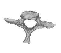
Mean - 3SD Mean + 3SD
Figure 4: Instances generated from the model of the C7 vertebra. The first three modes are varied acrossthree standard deviations. The modes are organized in rows, with the left vertebra for each pair being themean shape minus three standard deviations (SD), and the right vertebra being the mean plus three SD. Themean shape appears in the middle of the figure.
cal analysis on the ten resulting meshes, and inves-
would not be desirable, as it would mean that the
tigated the model that was created from this train-
correspondences are incorrect, and would lead to
ing set. Figure 4 shows some instances generated
non-viable instances for certain values of the mode
from the model. Here the first three modes are var-
ied across three standard deviations. The modes are
Because one of the primary reasons for using a
organized in rows, showing the mean shape minus
PDM is the ability of this model to describe the data
three standard deviations (SD), and the mean plus
with a small number of degrees of freedom, we in-
three SD. The mean shape appears in the middle of
vestigated how much variability was described by
each mode of variation. Figure 5 shows the per-
The modes correspond to physical aspects of the
centage of shape variance described by the first ✟
vertebra. The third mode, for instance, corresponds
modes. Ideally, if there is little variation in the train-
to a variation in length of the transverse processes.
ing set, we should be able to explain most of it with
This fits well with our intuition that the variation
a smaller number of modes. As can be seen, we can
across the training set should show variations in
describe 88% of the variance using only five modes.
widths, lengths, etc. In addition, because the struc-
The final aspect of the model that we investigated
tures are symmetric, we expect the variations to
was the accuracy of the mesh representation of the
also be symmetric, which we observe in this figure.
training set shapes using various numbers of modes.
There is not a noticeable twisting effect among the
modes, which demonstrates that the vertices on the
fully reconstruct each training sample, and then re-
meshes did not slide across the surfaces. Sliding
Number of Modes Number Of Modes
Figure 5: The cumulative shape variance described
Figure 6: The residual error using the first
of variation to describe the training set. The error
with zero modes we are using the mean mesh to
here measures the distance from each vertex recon-
represent each surface, so none of the variance is ex-
plained. With all modes, however, the entire train-
in the true mesh. These distances are then averaged
ing set can be described perfectly. With five modes,
we can explain 88% of the variation.
over similar existing methods, which require a pre-
segmentation of every shape in the training set.
Results from the creation of a C7 vertebral
mal method for compressing the shape representa-
model showed that an accurate representation can
tion, i.e., causes the least loss in accuracy. The met-
be achieved (with a mean surface distance of about
ric used to measure accuracy was the residual er-
1 mm) by warping the template mesh to correspond
ror between the reconstructed mesh vertex and the
to the appropriate training image. In addition, the
true mesh vertex (the mesh produced by warping the
shape model can describe the mesh to an accuracy
template mesh), measured in millimeters.
of about 1 mm using only five modes of variation.
Figure 6 shows the mean and maximum residual
The performance of our method is comparable to
a study done by Kaus et al. [2]. They used images
each shape in the training set. Notice that even if
with a slice thickness of 2.0 mm, and a similar range
we use only the mean shape (no modes of varia-
of in-plane resolutions. They were able to obtain a
tion) to reconstruct each mesh, we still see only 2
mean surface distance of 0.8 mm, and a mesh accu-
mm of mean residual error. This means that across
racy of 1.6 mm with ten modes (they used a set of 32
most of the vertices in a given mesh, most of them
vertebrae, including L1-L4). Their results required
do not deviate very far from their mean value. We
a prior segmentation of every shape, however, and
can also see that, as expected, the error goes to zero
we believe the savings in time using our method are
when we use all nine modes. It is a mathematical
worth the slight decrease in surface representation
consequence of PCA that we can reconstruct all ten
accuracy. In addition, for most applications, it is
training vectors perfectly if we use all nine modes.
likely that an accuracy of 1 mm should be sufficient.
Their method treats the affine-transformed mesh
as an active surface, and allows the mesh to deform
Discussion and Conclusion
so as to push the mesh vertices towards the bound-aries in the volumetric image. While their input im-
In this paper we have presented an automatic pro-
ages consist of white foreground pixels on a black
cedure for the construction of 3D statistical shape
background, this process would likely work with
models. The method requires the manual segmen-
the original grayscale image. As a result, we be-
tation of only one image in the training set, and gen-
lieve that this technique could also be applied to our
erates the surfaces and provides correspondences
warped meshes, and work is underway to refine the
mesh after the non-rigid warping step to improve its
[5] T. McInerney and D. Terzopoulos.
accuracy. Additional refinement of the mesh should
formable models in medical images analysis:
help to push the vertices closer to the boundaries,
a survey. Medical Image Analysis, 1(2):91–
creating a more accurate surface representation.
The experiments described above were per-
[6] R. R. Paulsen and K. B. Hilger. Shape mod-
formed on a small set of ten CT images, and we
elling using markov random field restoration
believe that it is important to evaluate the method
of point correspondences. In Information Pro-
on a larger set. We hope to obtain a larger set of
cessing in Medical Imaging, volume 2732 of
images and build a model from these in the future. LNCS, pages 1–12. Springer-Verlag, 2003.
Because registration with NMI has been shown to
[7] A. F. Frangi, D. Rueckert, J. A. Schnabel, and
work across imaging modalities, we do not require
W. J. Niessen. Automatic 3D ASM construc-
a training set confined to one modality. Because of
tion via atlas-based landmarking and volumet-
this, we may be able to build larger training sets by
ric elastic registration. In Information Pro-
combining imaging data from a variety of sources. cessing in Medical Imaging, volume 2082 of
The quality of the model should improve with the
LNCS, pages 78–91. Springer-Verlag, 2001.
[8] D. Rueckert, A. Frangi, and J. A. Schnabel.
While our model results are comparable to mod-
Automatic construction of 3-D statistical de-
els generated with other methods, the true test of the
formation models of the brain using nonrigid
model is how well it works when applied to various
registration. IEEE Transactions on Medical
segmentation and image analysis tasks. This tech-
Imaging, 22(8):1014 –1025, 2003.
nique should work for any shape and is sufficiently
[9] E. N. Mortensen, B. S. Morse, W. A. Bar-
general to provide many future opportunities.
rett, and J. K. Udupa. Adaptive boundary de-tection using ‘live-wire’ two-dimensional dy-namic programming. ACKNOWLEDGEMENT of Computers in Cardiology, pages 635–638,1992.
The authors thank Daniel Rueckert, Department of
[10] W. Schroeder, K. M. Martin, and W. E.
Computing, Imperial College London, for extended
discussions and valuable feedback about this work. Object-Oriented Approach to 3D Graphics(2nd ed.). Prentice-Hall, 1998.
[11] T. Rohlfing and Jr C. R. Maurer. Non-rigid
References
image registration in shared-memory multi-processor environments with application to
[1] T. F. Cootes, C. J. Taylor, D. H. Cooper, and
brains, breasts, and bees. IEEE Transactions
J. Graham. Active shape models – their train-
on Information Technology in Biomedicine,
ing and application. Computer Vision and Im-age Understanding, 61(1):38–59, 1995.
[12] D. Rueckert, L. I. Sonoda, C. Hayes, D. L. G.
[2] M. R. Kaus, V. Pekar, C. Lorenz, R. Truyen,
Hill, M. O. Leach, and D. J. Hawkes. Non-
rigid registration using free-form deforma-
PDM construction from segmented images us-
tions: Application to breast MR images. IEEE
ing deformable models. IEEE Transactions onTransactions on Medical Imaging, 18(8):712–
Medical Imaging, 22(8):1005–1013, 2003.
[3] R. H. Davies, T. F. Cootes, and C. J. Taylor. A
[13] Colin Studholme, Derek L. G. Hill, and
minimum description length approach to sta-
David J. Hawkes. An overlap invariant en-
tistical shape modelling. In Information Pro-cessing in Medical Imaging, volume 2082 of
Pattern Recognition, 32(1):71–86,
LNCS, pages 50–63. Springer-Verlag, 2001.
[14] J. C. Gower. Generalised Procrustes analysis.
of point-based D statistical shape models for
Psychometrika, 40:33–51, 1975.
anatomical objects. Computer Vision and Im-age Understanding, 77(2):175–191, 2000.
M. K. JUCHHEIM GmbH & Co JUMO Instrument Co. Ltd. JUMO PROCESS CONTROL INC. Data Sheet 90.9722 Terminal heads and blocks ■ for thermocouples and resistance thermometers ■ terminal heads in different materials ■ Protection IP65 max. ■ versions for lead sealing Terminal heads (pages 1 to 4) DIN 43 729 specifies the terminal head forms A and B, which differ
hAir reseArch ANd scieNce esT., VAduz, liechTeNsTeiNrogaine is the major brand name for minoxidil, which appears to slow or stop hair loss for many users. in many cases it also promotes temporary hair regrowth, especially for men under age 40 losing hair from the crown area. Although relatively ineffective in treating receding frontal hairlines and men over 40, minoxidil is the lowest cost hair
 Automatic Generation of Shape Models Using Nonrigid Registration


 Training
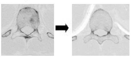


 age, and should lie on the surface of the structure ifthe nonrigid transformation is accurate. The appli-cation of the transformation corresponding to eachtraining sample is shown in Fig. 1, resulting in a setof such surfaces with vertex correspondences.
 The principal components (or principal axes) of this
distribution are then given by the eigenvectors of the
sponding to the largest eigenvalues as columns, we
Training Sample
The principal components (or principal axes) of this
distribution are then given by the eigenvectors of the
sponding to the largest eigenvalues as columns, we
Training Sample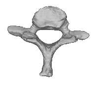


 Mean - 3SD